
Implement Virtual Surveillance IP Camera System (SICS) in Aviation Airport Runway Cyber Twin
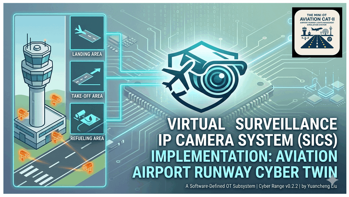
Project Design Purpose : The primary objective of this project is to design and implement a virtual Surveillance IP Camera System (SICS) that simulates the core functional components of an airport runway surveillance environment within the Mini OT Aviation CAT-II Airport Runway Simulation Cyber Range (version : v_0.2.2). This virtual SICS provides a fully software-defined representation without any specific hardware. It models the essential visual monitoring capabilities commonly found in the airport OT–IT integrated environments such as IP-based surveillance cameras, Air Traffic Control (ATC) tower monitoring dashboard, Video storage and retrieval systems.
This article is structured into three main sections:
-
Introduction to Runway Virtual SICS : A overview of the Surveillance IP Camera System, including its architecture, background, and operational role within the airport runway cyber twin environment.
-
Runway Virtual SICS Design : A detailed description of the system architecture, individual components, network configuration, communication protocols, and data storage mechanisms.
-
Use Cases and System Configuration : Demonstration of the monitoring dashboard UI, practical usage scenarios, and step-by-step configuration of the virtual SICS within the aviation cyber range.
Important : The real-world Surveillance IP Camera System deployed in airport environments is more complex and involves highly specialized, safety-critical infrastructure. This project does not aim to provide a 1:1 digital twin replication. Instead, it delivers a purpose-driven cyber twin abstraction that captures the essential operational and security-relevant characteristics of the system, enabling effective use in training, research, and cybersecurity exercises.
# Author:      Yuancheng Liu
# Created:     2026/04/12
# Version:     v_0.1.2
# Copyright:   Copyright (c) 2026 Liu Yuancheng
# License:     GNU General Public License V3
1. Project Introduction
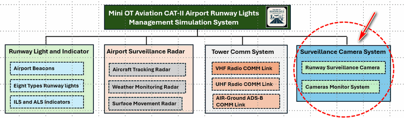
This project is one of the four main OT sub-system within the Mini OT Aviation CAT-II Airport Runway Simulation Cyber Range as shown in the below project structure diagram. Within the cyber range, the Runway Surveillance IP Camera System (SICS) acts as a key subsystem that provides real-time visualization feedback of the cyber twin's runway activities, including aircraft movement and ground operations.
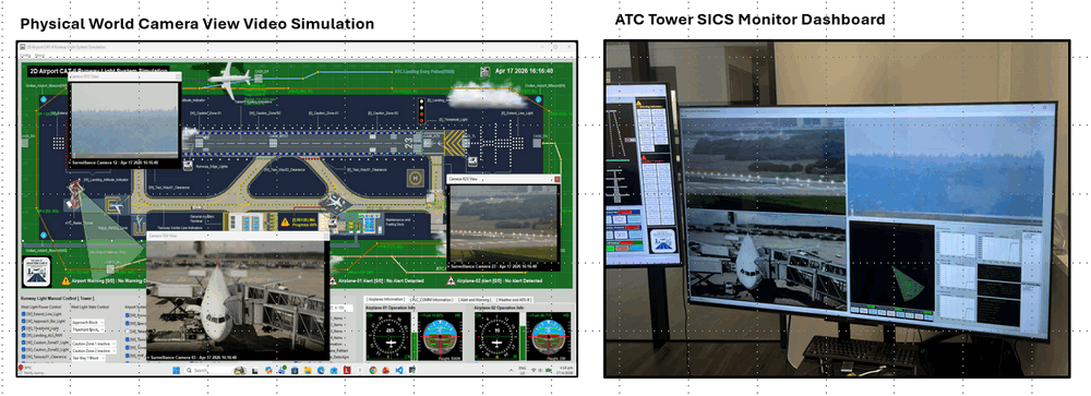
I aim to simulate multiple fixed angle daytime IP cameras deployed around the main runway, supporting airport ground operations and enhancing situational awareness for Air Traffic Control (ATC) monitoring and decision-making. The image below demonstrate the usage case of the SICS in the cyber exercise:
The system will focus on the core functional components, system architecture, and data flow across OT and IT environments. By abstracting key elements such as IP cameras, video management systems, and storage services, the project provides a practical platform for the usage of cybersecurity training, system behavior analysis and attack + defense simulation.
1.1 Abstract and Background
The Runway Surveillance IP Camera System (SICS) is a critical component of modern airport infrastructure, providing real-time visual monitoring to support safe and efficient airport traffic control operations. The system must deliver high levels of visibility, reliability, and coordination under both normal and adverse conditions. It enables continuous observation of runway conditions, aircraft movements, and ground activities, thereby enhancing situational awareness for operators in the Air Traffic Control (ATC) tower and airport operations centers.
A typical SICS consists of several interconnected components across both Operational Technology (OT) and Information Technology (IT) domains, including:
-
IP Cameras (fixed, PTZ, thermal) deployed along runways and taxiways
-
Communication Networks enabling real-time video transmission
-
Video Management Systems (VMS) for centralized control, visualization, and analytics
-
Record Storage Systems for recording and playback of surveillance data
-
Operator Interfaces (HMI) located in ATC towers or control rooms
1.2 Problem State Identification
As part of a software-defined aviation cyber twin, the implementation of SICS introduces several technical challenges need to be solved as list below :
-
Realistic video generation : How to generate camera video streams that accurately reflect the simulated physical world (e.g., aircraft movement, runway status).
-
System realism under adversarial conditions : How to ensure the virtual cameras behave similarly to real devices when subjected to red team activities (e.g., spoofing, scanning, or exploitation).
-
Time synchronization and interaction consistency : How to synchronize video streams and system states with other cyber twin components (e.g., runway lighting systems, control signals, and events).
1.3 Technical Stack State
The Python-based virtual camera module Python Virtual Motion-JPEG Camera Simulator was developed to address these challenges introduced in section 1.2 . This module enables the generation of realistic Motion-JPEG video streams from simulated environments, allowing the virtual cameras to :
-
Mimic real IP camera behavior at the video transmission protocol level.
-
Integrate into OT networks (blue team) and the airport cyber range physical world simulator module.
-
Support cybersecurity exercises with realistic attack surfaces with the customized vulnerability configuration.
2. IEC-62264 System Architecture
Within the cyber range, the SICS is mapped onto five different programs allocated in four-layer IEC 62264 industry standard, the five main components distributed across these layers are shown in the following diagram :
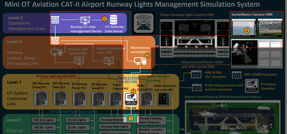
[1] Fixed Cameras Video Generator (Layer 0 – Physical Process Level)
This component represents the physical layer of the system. It generates simulated video streams based on the state of the components in the cyber twin's physical world simulator module such as the aircraft movement, refueling progress and some other runway activities.
[2] Motion-JPEG Camera Simulator (Layer 1 – OT Control Level)
Connected into the OT-SCADA network, this component converts simulated video signal into Motion-JPEG video streams and simulate the behavior of real IP cameras. It serves as the interface between the physical world simulation and airport tower room monitoring system.
[3] Video Management System (Layer 2 – Supervisory Control Level)
Deployed within the airport tower room internal LAN (workstation), the VMS is responsible for:
-
Managing IP cameras' configurations and aggregating video streams from multiple sources.
-
Providing centralized raw camera motion-JPEG stream processing, monitoring and control.
[4] Camera Monitoring Dashboard (Layer 2 – Supervisory Control Level)
This dashboard provides a unified monitoring Human–Machine Interface (HMI) for ATC operators. It displays live video feeds and associated analytics, enabling real-time monitoring and decision-making.
[5] Record Storage System (Layer 3 – Operations Management Level)
Located in the operations management zone, this component includes a historian database server responsible for:
-
Recording surveillance videos.
-
Managing compressed video storage.
-
Supporting playback and forensic analysis.
3. System Design and Workflow
As shown in the previous section the implementation consists of four primary functional modules distributed across IEC 62264 layers collectively emulate a complete end-to-end video surveillance pipeline, from physical scene generation to centralized monitoring and long-term storage. The operation of the four main functional modules is shown in the below workflow diagram:
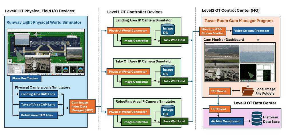
The four functional modules in the work flow includes:
-
Physical World CAM Lens Simulators : Three camera lens view simulation modules covering the Runway takeoff area, Runway landing area and Taxiway refueling area.
-
IP Camera Simulator: Three network IP camera simulation modules to fetch the video frame from the camera lens.
-
Tower Room Camera Manager : One tower room surveillance dashboard module to connect to the IP cameras to fetch the motion-JPEG video stream.
-
Historian Data Archiver : One historian data archive module running on historian DB server to linked to dashboard to archive the record.
3.1 Design of Physical World CAM Lens Simulator
The Physical World CAM Lens Simulator interfaces directly with the runway physical world simulator, translating simulated runway activity into camera-visible outputs and responsible for:
-
Tracking aircraft positions and states in real time.
-
Determining camera field-of-view coverage.
-
Generating image index references representing the current visual scene.
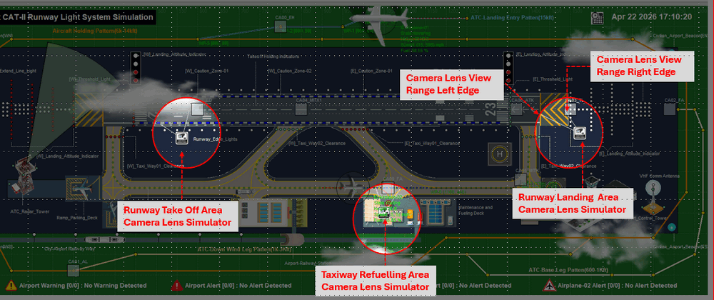
The Physical World Camera Lens Simulator includes 3 module : Airport Planes Ground Position Tracker, Camera Lens Simulation and Camera Image Index Data Manger. The three camera lens' position and their view range in the cyber twin's physical world simulation module is shown below:
3.1.1 Plane Position Tracker → View Frame Mapping
Each camera is associated with a plane position tracker that continuously monitors the aircraft position and ground movement state (e.g., taxiing, takeoff, baggage loading and refueling), the plane position-state and frame mapping implementation is shown in the below example:
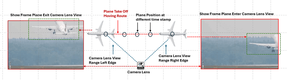
When an aircraft enters a camera’s field of view, the system:
-
Determines the plane relative position in the view window, viewing angle and current state.
-
Selects the appropriate visual frame representing that scenario based on the plane relative position and state.
3.1.2 Camera Lens Simulation
Each virtual camera is defined by a fixed position within physical world simulator (highlighted camera icon) and a configurable field-of-view (two dash line from the camera icon).
The system provides a visual interface where the users can click with the camera icon on the physical map, then the simulated “lens view” window will pop-up as shown below:
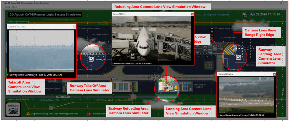
To simulate the "real view" from the lens direction aim to the related area of the airport, I pre-configured several GIFs image and the the pop-up lens window will play these GIFs based on the Plane Position Tracker's output.
3.1.3 Camera Image Index Data Manager
The Camera Image Index Data manager is part of the data manager module which will act as the communication interface between the physical simulator's camera lens and IP camera simulators:
-
Converts generated frames into image index identifiers for scalable to multiple cameras per scene.
-
Maintains mapping between scene state and image datasets to supports future extension (e.g., multiple cameras per zone).
-
Transmits index data via UDP to camera simulators to make a lightweight communication (no raw image transfer) channel.
3.2 Design of the IP Camera Simulator
Each IP Camera Simulator is implemented using the Python_Virtual_Motion-JPEG_Camera_Simulator module I developed. Three virtual machines simulate the independent IP cameras. Each instance:
-
Receives image index data from the physical simulator.
-
Maps indices to pre-generated image frames.
-
Converts frames into Motion-JPEG (MJPEG) video streams.
-
Exposes HTTP endpoints for real-time streaming.
This design allows each virtual camera to behave like a real networked surveillance device, including protocol-level interaction and potential attack surfaces. Each simulator consists of four core components:
3.2.1 Physical World Connector
Periodically connects to the physical world simulator module via UDP to fetch the current camera images' index matching information and maintains synchronization with real-time scene state.
3.2.2 Image Frame Database
Each camera will have image file data base stores pre-generated image frames representing all possible camera views Includes both the “empty scene” and “aircraft present” conditions. The images data base of take off camera are used as an example shown below :
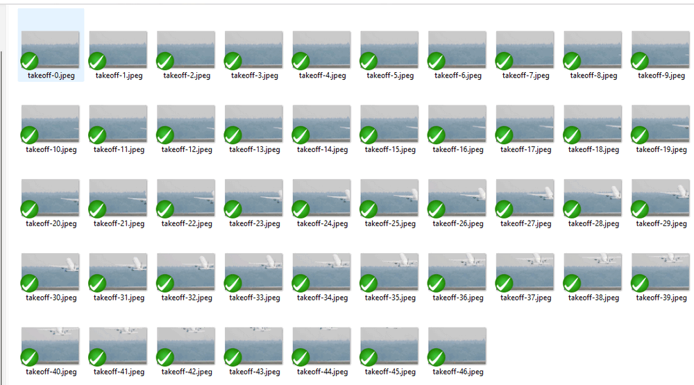
Each frame is indexed for controller module to fast lookup when used for motion-JPEG video stream generation.
3.2.3 Image Controller Module
The main controller module controls frame rate and streaming behavior with below two functions:
-
Maps the incoming image indices to the corresponding frames in the frames storage DB.
-
Assembles frames into a continuous Motion-JPEG stream for video fetching.
3.2.4 Flask Camera Host Module
A management web application that mimics Axis-style camera pages with below functions :
-
Provides a web-based camera management interface.
-
Mimics real-world IP camera systems (e.g., Axis-style UI) configuration function.
-
Exposes Live stream endpoints, configuration settings, user authentication and logs.
-
Provide realism for cyber exercises allowing vulnerability testing, credential attacks and web interface exploitation scenarios.
3.3 Design of Tower Room SICS Manager
The Tower Room SICS Manager simulates the operator-facing control system within the tower operation room ATC environment. This module provides below functions :
-
Periodically fetches Motion-JPEG streams from all camera simulators.
-
Aggregates and resizes streams into a unified multi-cameras display dashboard.
-
Integrates additional contextual data (e.g., radar, ADS-B, weather) in the main dashboard.
-
Stores combined frames locally for short-term usage.
-
Hosts an FTP server for data export to higher-level IT/OT systems.
In the cyber exercise simulated airport tower ATC control room, the will be two main screens show the dashboard :
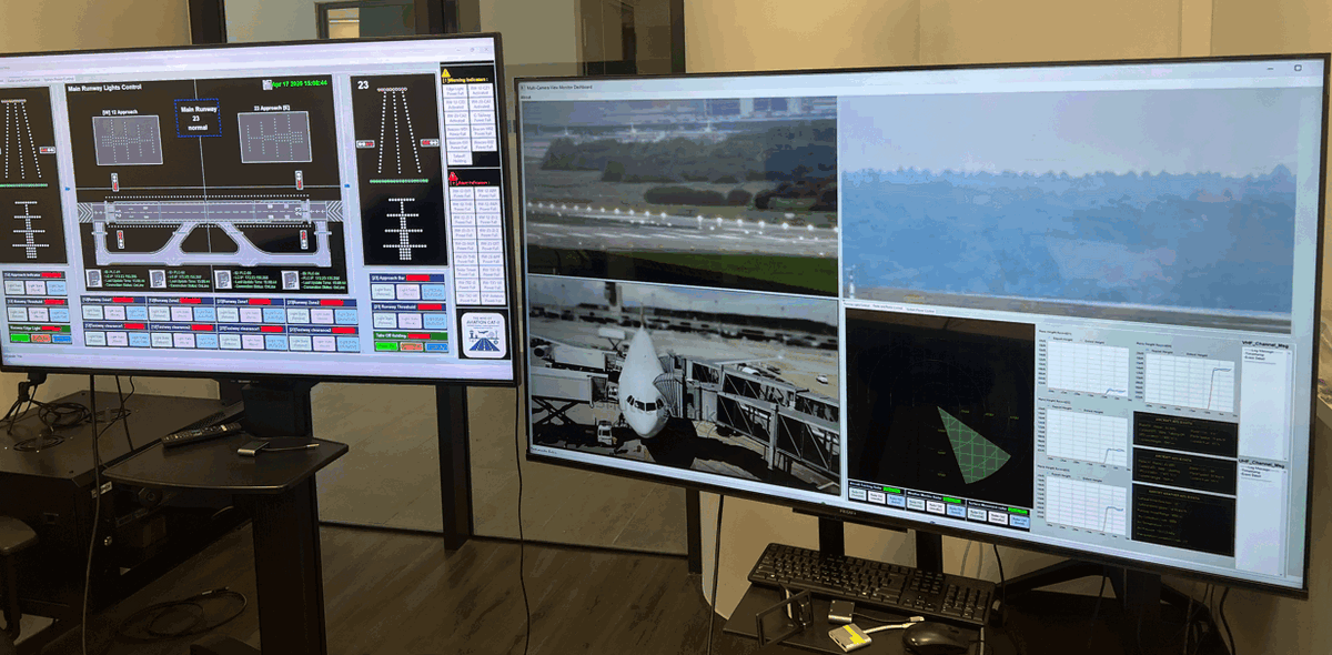
3.3.1 MJPEG Stream Fetcher
-
Running in sub-thread periodically retrieves video streams from all camera simulators via HTTP(s).
-
Ensures synchronization across multiple video(camera VM) sources.
3.3.2 Multi-Camera Monitor Dashboard (HMI)
Aggregates multiple streams into a unified interface and the display dashboard feature includes :
-
Configurable grid layout 2 x 2 size for customized display setups.
-
Adjustable stream FPS and resolution for performance tuning.
-
Allows multiple dashboards to subscribe to the same camera stream
The dashboard display integrates Radar data, ADS-B information, Weather updates and VHF communication logs with a common timestamp, enabling consistent situational awareness.
3.3.3 Local Storage and FTP Service
The dashboard view (combined 2x2 grid image will) will be saved in the Tower Room SICS Manager Program's record folder and the SICS Manager will start a FTP server with a sub-thread with the Python FTP module. The main functions includes :
-
Captures combined dashboard frames at every 0.3-second intervals.
-
Stores images locally for short-term access and usage.
-
Hosts an FTP server (via Python FTP module) to transfer data to the higher layer historian archive system.
3.4 Design of Video Archive Server
The Video Archive Server operates at the Operations Management Level and provides persistent storage mechanism. This module provides long-term storage and archival capabilities:
-
Periodically retrieves image data via FTP client.
-
Compresses data into time-based archives (e.g., hourly ZIP files).
-
Stores results in a historian database for searching request.
-
Supports offline analysis and forensic investigation.
3.4.1 Data Acquisition Function
-
Uses an FTP client to periodically retrieve images from the dashboard server VM.
-
Supports integration with higher-level analytics systems.
3.4.2 Data Archival Function
-
Groups the images into time-based collections (e.g., hourly).
-
Compresses data into archive files (ZIP format) then Stores archives in a historian database.
4. System Usage and Configuration
4.1 System Setup and Configuration
The system network configuration in the cyber range is shown in below cyber exercise deployment network topology :
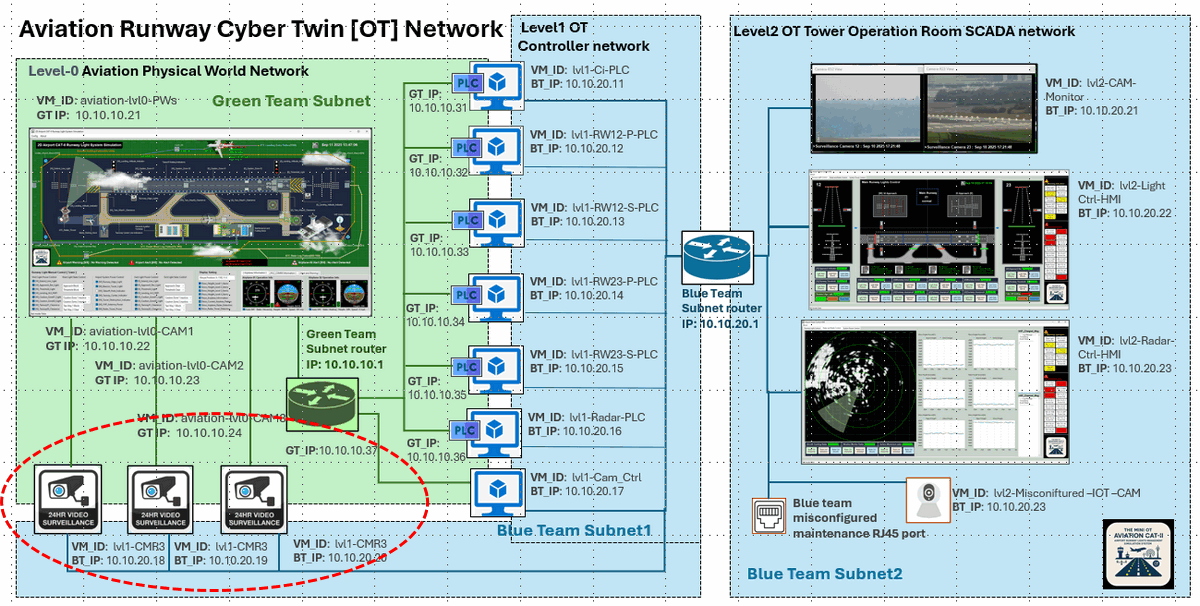
Each IP cameras VM will have 2 NIC one connect to the green team network router and one connect to the blue team network router.
4.1.1 Setup the landing area camera
In the landing area camera VM's configuration file src\virtualCameras\landingVirtualCam\Config.txt, change the parameters as shown below:
# Camera video source parameter:
# Simulated camera report to RW ID:
CAM_ID:RW_CAM_1
# Physical camera ID
CAM_IDX:1
CAM_FPS:5
# Simulated camera data set parameters:
CAM_DATA_DIR:landing
CAM_DATA_PREFIX:landing-
CAM_DATA_START_IDX:6
CAM_DATA_END_IDX:53
4.1.2 Setup the take off area camera
In the take off area camera VM's configuration file src\virtualCameras\takeoffVirtualCam\Config.txt, change the parameters as shown below:
# Camera video source parameter:
# Simulated camera report to RW ID:
CAM_ID:RW_CAM_2
# Physical camera ID
CAM_IDX:2
CAM_FPS:5
# Simulated camera data set parameters:
CAM_DATA_DIR:takeoff
CAM_DATA_PREFIX:takeoff-
CAM_DATA_START_IDX:6
CAM_DATA_END_IDX:57
4.1.3 Setup the refueling area camera
In the refueling area camera VM's configuration file src\virtualCameras\refuelingVirtualCam\Config.txt, change the parameters as shown below:
# Camera video source parameter:
# Simulated camera report to RW ID:
CAM_ID:RW_CAM_3
# Physical camera ID
CAM_IDX:3
CAM_FPS:5
# Simulated camera data set parameters:
CAM_DATA_DIR:refueling
CAM_DATA_PREFIX:refueling-
CAM_DATA_START_IDX:2
CAM_DATA_END_IDX:402
4.1.4 Change the dashboard connection configuration file
In the dashboard configuration file src\MultiCamViewDashboardcamera\Config.json setup the blue team network IP address and the size as shown below:
{
    "LandingVirtualCam": {
        "name": "Runway Lading Area Surveillance Camera ",
        "url": "http://10.10.20.18:5001/cgi-bin/mjpg/",
        "token": "myF1x3dT0k3n_LAND",
        "size": [640,480]
    },
    "TakeOFFVirtualCam": {
        "name": "Runway Takeoff Area Surveillance Camera",
        "url": "http://10.10.20.19:5001/cgi-bin/mjpg/",
        "token": "myF1x3dT0k3n_TAKEOFF",
        "size": [640,480]
    },
    "RefuelVirtualCam": {
        "name": "Taxiway Refueling Area Surveillance Camera",
        "url": "http://10.10.20.20:5001/cgi-bin/mjpg/",
        "token": "myF1x3dT0k3n_OP",
        "size": [640,480]
    },
    "InformationDashboardMinitorCam": {
        "name": "InformationDashboard Monitor Camera",
        "url": "http://10.10.20.21:5001/cgi-bin/mjpg/",
        "token": "myF1x3dT0k3n_PW",
        "size": [640,480]
    }
}
4.2 System Execution and Usage
After finished the configuration in section 4.1 , execute the system with below command.
Run the landing area camera with below command :
python src\virtualCameras\landingVirtualCam\webCamApp.pyRun the take off area camera with below command :
python src\takeoffVirtualCam\takeoffVirtualCam\webCamApp.pyRun the refueling area camera with below command :
python src\takeoffVirtualCam\refuelingVirtualCam\webCamApp.pyRun the dashboard program with below command :
python src\MultiCamViewDashboard\camDashboardRun.pyThen c heck whether all the cameras are connected as shown below:
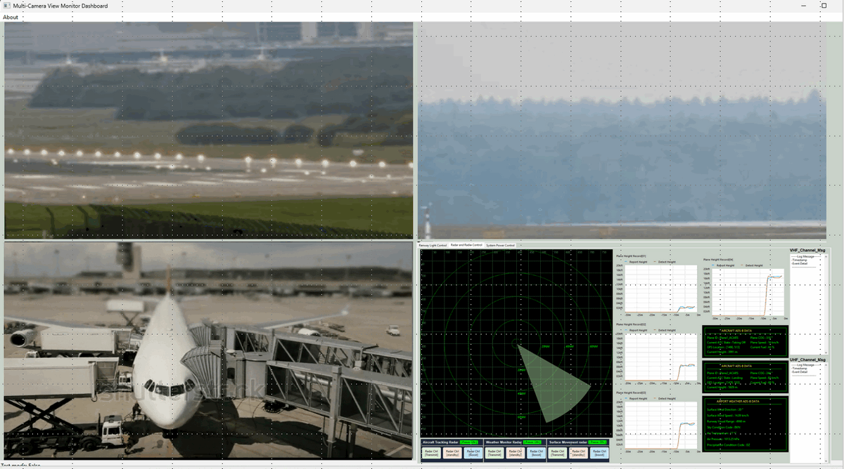
5. Conclusion and Reference
5.1 Conclusion
The implementation of the Virtual Surveillance IP Camera System (SICS) successfully establishes a robust, software-defined visual monitoring layer within the Mini OT Aviation Cyber Range. By aligning the system architecture with the IEC-62264 standard, this project demonstrates how complex OT-IT integrated environments can be abstracted into functional cyber twins without the need for high-cost physical hardware. The transition from physical world events—such as aircraft taxiing and refueling—to real-time Motion-JPEG streams provides a high-fidelity feedback loop essential for airport situational awareness.
Ultimately, while this system serves as a purpose-driven abstraction rather than a safety-critical replication, it effectively captures the operational logic and security vulnerabilities inherent in modern aviation infrastructure. The modular design, spanning from low-level camera lens simulators to high-level historian archives, offers a versatile platform for:
-
Cybersecurity Training: Providing realistic attack surfaces for red team exploitation and blue team monitoring.
-
System Analysis: Evaluating the interaction consistency between visual data and other airport OT subsystems.
-
Research & Development: Testing new surveillance protocols and data management strategies in a risk-free environment.
Moving forward, the SICS provides a scalable foundation for integrating more advanced features, such as PTZ (Pan-Tilt-Zoom) controls and AI-driven video analytics, further enhancing the depth of the aviation cyber twin.
5.2 Related Link
-
https://github.com/LiuYuancheng/Python_Virtual_MotionJPEG_Camera
-
https://github.com/LiuYuancheng/Python_FTP_Server_and_Client
Thanks for spending time to check the article detail, if you have any question and suggestion or find any program bug, please feel free to message me. Many thanks if you can give some comments and share any of the improvement advice so we can make our work better ~
last edit by LiuYuancheng ([email protected]) by 26/04/2026 if you have any problem, please send me a message.

No comment for this article.