

Project Design Purpose : This article will introduce the detailed design methodology and functional objectives for implementing the Warning, Alarm, and Fault Alert Sub-System within the Mini OT Aviation CAT-II Airport Runway Lights Management Simulation System (version : v_0.2.2). This subsystem plays a crucial role in supporting cyber exercise and incident response training which focused on airport operational technology (OT) safety, reliability, and cybersecurity awareness by using the cyber range system.

This design document introduces the following three core development areas:
-
Alert Logic and Scenario Simulation : Detailed design of programmable conditions to trigger warnings, alarms, and fault alerts within the aviation cyber range.
-
User Interface Indicators and Display Effects : Visual representation of alarm states in both the physical world simulator and tower ATC Human-Machine Interface (HMI), ensuring intuitive, operationally realistic feedback.
-
PLC Setup for Fault Detection : Development of control logic that continuously monitors simulated components to detect possible electrical/control faults and initiate appropriate alert responses.
# Author:      Yuancheng Liu
# Created:     2025/11/25
# Version:     v_0.2.2
# Copyright:   Copyright (c) 2025 Liu Yuancheng
# License:     GNU General Public License V3
Introduction
The modern airports rely on highly sophisticated Runway Light Warning and Fault Alert Systems to ensure safe aircrafts operations during takeoff, landing, taxiing, and emergency scenarios. In real-world airport operations, runway lighting systems are essential for aircraft navigation, especially under low-visibility conditions. Any operational anomaly—whether a lighting failure, electrical disturbance, or unauthorized control action—poses significant safety risk. Therefore, runway control towers rely on comprehensive alerting mechanisms to monitor system health and guide safe decision-making.
To accurately replicate this operational environment, the aviation cyber range includes a virtualized runway lights abnormal detection management module capable for generating realistic warning and alarm scenarios for both tower ATC operators and maintenance engineers:
-
Warning and Alarm Simulation for Operational Control : Tower ATC officers require timely alerts to manage aircraft traffic safely. The system simulates visual and audible alarms triggered by abnormal states, such as runway stop bar failures or reduced lighting intensity.
-
Fault Detection and Alert Mechanism for Engineering Response : Maintenance personnel rely on fault diagnostics to identify root causes. The simulation incorporates electrical-based failure detection—such as power loss and component malfunctions—to support troubleshooting exercises.
The aviation runway simulation cyber twin system typically categorizes alerts into warnings, alarms, and fault notifications, each representing a different level of operational impact. The system provides 11 types of runway warning, 16 types of runway alarm, 4 types of infra alarm and 5 types of aircraft alert for simulating different abnormal scenarios (As shown below).

Figure-01: Overview of different type of warning and alarm v0.2.1 (2025)
General Warning Notifications indicate conditions that require ATCO attention but do not immediately compromise safety. These may include reduced brightness levels, minor degradation in lamp output, or early-stage power fluctuations.
Alarm Scenarios are triggered when critical runway lighting elements are malfunctioning or become unavailable. Examples include loss of stop bar control, complete power off for approach lighting, or sudden blackout of runway edge lights. Alarms demand immediate corrective action and may require closing the runway until the issue is resolved.
Fault Alerts provide detailed diagnostic information about electrical, communication, or equipment-level failures. These may include light power failure, cable insulation breakdown or unresponsive remote control modules. Fault alerts are essential for maintenance teams to quickly isolate the defective component and restore full functionality.
Warning and Alarm Trigger Scenarios
The warning and alarm subsystem supports realistic simulation of operational anomalies in the cyber range environment with an abnormal scenarios detection program. If the current physical world simulator scenario doesn't match the pre-configured safety condition in the abnormal scenarios detection program, the program will raise different kind of warning and alarm. A total of 11 runway warnings, 22 runway alarms, and 5 aircraft alert types are implemented to represent potential abnormal conditions that air traffic controllers (ATCOs) and maintenance teams may encounter.
This section describes the trigger logic for each category and the associated alert messages displayed on the physical simulation environment and HMI interfaces. For the condition trigger logic we follow the "Chapter 6. Emergency Procedures" and "Chapter 7. Safety of Flight" in the FAA ATC generical information guide book: https://www.faa.gov/air_traffic/publications/atpubs/aim_html/
Runway Warning Trigger Scenarios
Runway warnings indicate conditions that require operator attention but do not immediately compromise runway safety or interrupt ATC operations. These scenarios usually reflect minor issues such as reduced visual aids or partial system degradation. ATCOs must report and track these warnings, ensuring they are resolved within a required timeframe, especially if not caused intentionally during operational procedures.
The warning sign and message will show next to the abnormal components in the cyber range's physical world simulator as shown below :
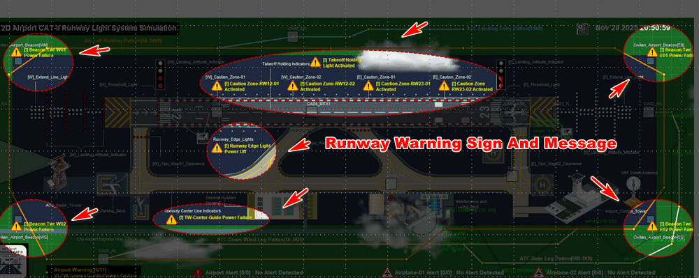
Figure-02: Warning sign and message on physical world simulator v0.2.1 (2025)
For the message and related abnormal scenario, the detail is shown in the below table :
| Index | Warning Message (HMI / PW Simulator) | Trigger Scenario Description |
|---|---|---|
| 1 | [!] Runway Edge Light Power Off | Runway edge lights turned off during daytime |
| 2 | [!] Caution Zone-RW12-01 Activated | Runway 12 – West caution zone indicator active (Yellow) |
| 3 | [!] Caution Zone-RW12-02 Activated | Runway 12 – Middle caution zone indicator active (Yellow) |
| 4 | [!] Caution Zone-RW23-01 Activated | Runway 23 – Middle caution zone indicator active (Yellow) |
| 5 | [!] Caution Zone-RW23-02 Activated | Runway 23 – East caution zone indicator active (Yellow) |
| 6 | [!] TW-Center-Guide Power Failure | Taxiway centerline guidance indicator power off |
| 7 | [!] Beacon Twr W01 Power Failure | NW civilian airport boundary area beacon tower power failure |
| 8 | [!] Beacon Twr W02 Power Failure | SW civilian airport boundary area beacon tower power failure |
| 9 | [!] Beacon Twr E01 Power Failure | NE civilian airport boundary area beacon tower power failure |
| 10 | [!] Beacon Twr E02 Power Failure | SE civilian airport boundary area beacon tower power failure |
| 11 | [!] Takeoff Holding Light Activated | Takeoff holding light switched on (not under takeoff operation) |
Runway Alarm Trigger Scenarios
Runway alarms involve several lighting failures or system malfunction conditions that may directly affect aircraft landing or takeoff safety. When an alarm is triggered, ATCOs must immediately initiate troubleshooting checklists and, if necessary, halt runway operations.
Runway-12 Alarm Scenarios
The Runway-12 alarm sign and message will show next to the abnormal and caution components in the cyber range's physical world simulator as shown below :

Figure-03: Runway-12 alarm on physical world simulator v0.2.1 (2025)
For the 8 types of alarm message and related abnormal scenario, the detail is shown in the below table :
| Index | Alarm Message (HMI / PW Simulator) | Trigger Scenario Description |
|---|---|---|
| 1 | [X] Runway-12 Extend Light Power Failure ! | Runway-12 centerline extension lights power loss |
| 2 | [X] Runway-12 Approach Bar Power Failure ! | Runway-12 approach lighting bar power loss |
| 3 | [X] Runway-12 Threshold Bar Power Failure ! | Runway-12 threshold wing bar and supplementary approach power loss |
| 4 | [X] Runway-12 PAPI Power Failure ! | Runway-12 PAPI (Precision Approach Path Indicator) power loss |
| 5 | [X] RW12 Zone01 Indicator Power Failure ! | Runway-12 west caution zone indicator power loss |
| 6 | [X] RW12 Zone02 Indicator Power Failure ! | Runway-12 middle caution zone indicator power loss |
| 7 | [X] RW12 Taxi Exit Indicator Power Failure ! | Runway-12 taxiway exit clearance light power loss |
| 8 | [X] RW12 Taxi Entrance Indicator Power Failure ! | Runway-12 taxiway entrance clearance light power loss |
Runway-12 Alarm Scenarios
The Runway-23 alarm sign and message will show next to the abnormal and caution components in the cyber range's physical world simulator as shown below :
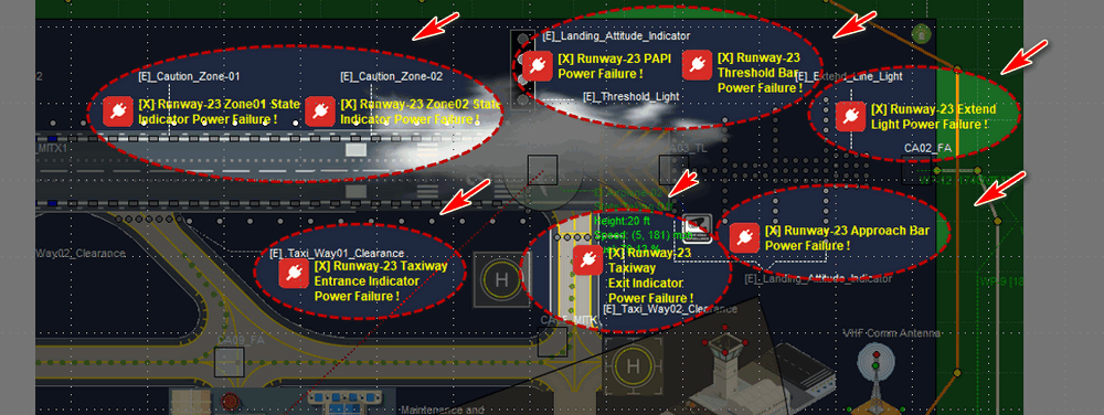
Figure-03: Runway-23 alarm on physical world simulator v0.2.1 (2025)
For the 8 types of alarm message and related abnormal scenario, the detail is shown in the below table :
| Index | Alarm Message (HMI / PW Simulator) | Trigger Scenario Description |
|---|---|---|
| 1 | [X] Runway-23 Extend Light Power Failure ! | Runway-23 centerline extension lights power loss |
| 2 | [X] Runway-23 Approach Bar Power Failure ! | Runway-23 approach lighting bar power loss |
| 3 | [X] Runway-23 Threshold Bar Power Failure ! | Runway-23 threshold wing bar and supplementary approach lights off |
| 4 | [X] Runway-23 PAPI Power Failure ! | Runway-23 PAPI power failure |
| 5 | [X] RW23 Zone01 Indicator Power Failure ! | Runway-23 Middle caution zone indicator failure |
| 6 | [X] RW23 Zone02 Indicator Power Failure ! | Runway-23 East caution zone indicator failure |
| 7 | [X] RW23 Taxi Exit Indicator Power Failure ! | Runway-23 Taxiway exit clearance light failure |
| 8 | [X] RW23 Taxi Entrance Indicator Power Failure ! | Runway-23 Taxiway entrance clearance light failure |
Airport Infrastructure Alarm Scenarios
For the 4 types airport infrastructure message and related abnormal scenario, the detail is shown in the below table :
| Index | Alarm Message (HMI / PW Simulator) | Trigger Scenario Description |
|---|---|---|
| 1 | [X] Runway Edge Light Power Off ! | Runway edge lights off during nighttime operation |
| 2 | [X] Radar Antenna Power Failure ! | Airport surveillance radar power disruption |
| 3 | [X] VHF Antenna Tower Power Failure ! | VHF/UHF communications antenna power failure |
| 4 | [X] Tower Obstruction Indicator Failure ! | Airport Building obstruction warning lights on tower not functioning |
Aircraft Alarm Trigger Scenarios
The aircraft will also report alert to the airport tower when they following the ATC role or the simulated pilot detect some thing abnormal, the aircraft alarm sign and message will show on the plane and the alert message will show next to the plane.(As shown below)

Figure-04: Aircraft alarm on physical world simulator v0.2.1 (2025)
For the 5 types of aircraft alarm message and related abnormal scenario, the detail is shown in the below table :
| Index | Alarm Message Shown on physical world | Alarm Scenario Description |
|---|---|---|
| 1 | [x] Airplane Fuel Low ! | Airplane Fuel reach/under 12% level |
| 2 | [x] Final Approach Cancel Emergency Climbing UP... | Airplane cancel final approach procedure in landing, do the emergency climbing up to holding flight pattern. |
| 3 | [x] Airplane Front Radar Possible Collision. | Airplane front radar detect other plane in 10min range in same flight pattern |
| 4 | [x] Detect Landing Procedure Takeoff Postponing... | Airplane moving from taxi way to take off prepare area and detect other plane is doing the final approach process. |
| 5 | [x] VHF instruction conflict ! | The VHF instruction conflict with the current light state. |
PLC-HMI Fault Alert Handling Feature
To enhance the realism and operational depth of the Mini OT Aviation Runway Light Management Cyber Twin System, a PLC-based component fault alert handling mechanism has been implemented. This feature simulates the real-world electrical behavior and fault detection workflow used in airport runway lighting systems, enabling both OT engineers and cyber defenders to practice diagnosing operational faults and cyber-induced anomalies.
To implement this feature, each light's PLC control includes below feature:
-
A motorized control breaker (for switching power on/off)
-
A current metering unit (MU)
-
A light state sensor
-
PLC changeable points (C_CR_TA_1)
-
PLC measurement points (M_SP_NA_1)
The HMI continuously compare the commanded action and the PLC feedback state, If a mismatch occurs, the system triggers a component fault alert visible to the tower ATCO. The PLC–component–HMI workflow is shown in below diagram:
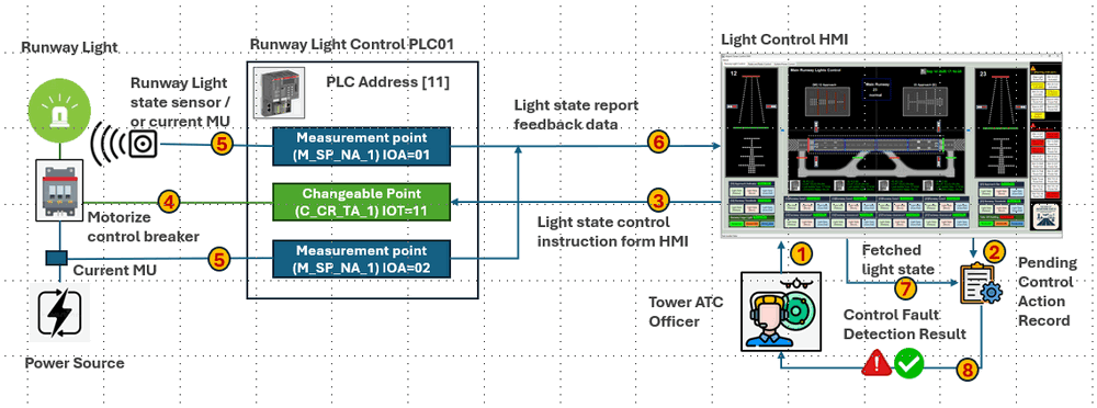
Figure-05: PLC-HMI Fault Alert Handling workflow diagram, v0.2.2 (2025)
The system follows an 8-step process to detect component failures and abnormal behaviors:
Step 01 – ATCO Initiates a Light Control Action
-
The tower operator selects a light control (e.g., turn on Takeoff Holding Light) and confirms the action via the command confirmation dialog.
Step 02 – HMI Records Pending Control Action
-
The HMI program logs the command as “pending” in its control action record table, awaiting verification from PLC feedback.
Step 03 – HMI Sends IEC-104 Command to PLC
-
The HMI issues an IEC-104 write command to update the PLC’s changeable point (IOA) that controls the target light.
Step 04 – PLC Controls Motorized Breaker
-
The PLC simulator updates the output coil, causing the motorized breaker in the physical-world simulator to switch ON/OFF and change the light’s electrical state.
Step 05 – Sensors Report Actual Light Behavior
-
The current metering unit and light state sensor generate real-time physical feedback (current flow, light ON/OFF) collected by two PLC measurement points.
Step 06 – HMI Fetches PLC Feedback Data
-
During the next HMI execution cycle, the HMI retrieves sensor readings, breaker status, and PLC state values through IEC-104.
Step 07 – HMI Compares Expected vs. Actual State
-
The HMI compares the pending command with the actual light state and measured electrical current. If any mismatch is detected, a component fault alert is generated.
Step 08 – UI Displays Normal or Fault Condition
-
A green indicator shows normal operation (command and electrical state match).
-
A red fault popup appears if a physical or electrical inconsistency is detected.
Fault Detection Logic Table
This comparison table illustrates how the system interprets mismatched states to identify possible component failures:
| ATCO Action | Light Sensor Result | Current MU Value | Possible Fault Alert |
|---|---|---|---|
| Turn ON takeoff holding light | Light OFF | 0 A | Light spoiled / lamp malfunction |
| Turn ON takeoff holding light | Light OFF | > 0 A | Possible short circuit |
| Turn OFF takeoff holding light | Light ON | > 0 A | Motorized breaker failure |
This logic accurately simulates real OT maintenance diagnostic processes.
Cybersecurity Perspective: Detecting MITM and OT Manipulation Attacks
As the cyber twin system is used in the cyber exercise, the component fault alert handling function can also be used for detecting the possible red team hacker's OT attacks action in the system such as MITM attack. In the cyber range exercise scenario described in Aviation Runway Cyber Range OT Security Case Study 02: MITM Attack on PLC-HMI IEC104 Channel , if the attacker modifies the ATCO’s control command without altering the PLC’s feedback data, as shown below:
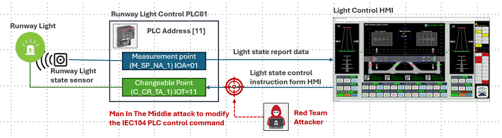
Figure-06: Possible MITM attack workflow diagram, v0.2.2 (2025)
If the attacker doesn't change the PLC feed back data with the correct value which can match the modified action he has done, then at the blue team side who are monitoring the tower HMI, then will detect the control fault alert and trace the attack action.
Design of Warning and Alarm UI Indicators
The system includes two distinct visual interfaces for alerting the user to abnormal runway lighting conditions:
-
The Physical World Simulator, representing real-time component abnormal status in the cyber-physical twin.
-
The Tower ATC HMI, presenting validated system state and abnormal state information based on PLC feedback and authorized control operations.
Although both interfaces display warning and alarm signals, their triggering logic and visual behavior differ based on the intended operational role.
Physical World Simulator – Warning and Alarm Display
The physical simulator replicates real-world behavior by directly reflecting the status of physical components. Whenever a runway device transitions into an abnormal state (e.g., loss of power, malfunction, operational inconsistency), as shown in the picture in "Runway Warning Trigger Scenarios" and "Warning and Alarm Trigger Scenarios" the system will:
-
Flash a warning/alarm icon near the affected component
-
Display a contextual message beside the malfunctioning asset
-
List alerts continuously through a bottom scrolling indicator for White Team situational monitoring
There are also another 4 different indicators at the physical world simulator's bottom area rolling play all the warning and alarm messages for the cyber exercise white team to monitor as shown below :

In addition, selecting the Warning & Alarm tab in the notebook area shows the history log of triggered alerts, including timestamps for traceability and cybersecurity training review:
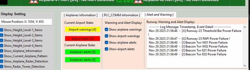
This presentation gives operators a complete operational picture of the ongoing system state during cyber exercise scenarios.
Tower ATC HMI – Warning, Alarm and Fault Alert Display
Alert representation in the Tower HMI follows stricter operational logic, adhering to realistic Air Traffic Control workflows. Here, warnings and alarms are triggered only when the PLC detects a fault condition that is not intentionally commanded by the ATC operator.
For example: If the runway edge lights are switched off by direct ATC instruction because of some reason, the HMI will not trigger a warning, even though the physical simulator shows a[!] Runway Edge Light Power Off warning.
This approach ensures:
-
No false alarms when actions are authorized
-
Accurate decision support for tower controllers
-
Clear differentiation between system failure and operator intention
The HMI warning and alarm indicators are all align at the right side of the tower HMI as shown below:

All alert indicators are displayed in a vertical stack on the right side of the HMI screen. When active:
-
Yellow indicators flash for warnings
-
Red indicators flash for critical alarms or equipment faults
If the instructor turn off the power of centerline extension lights in the physical world it will trigger the [X] Runway Extend Light Power Failure ! alarm, it the physical world simulator it will show the red alarm sign, but as it is the control action from the tower ATC, in the tower HMI, the alarm will shown as yellow color.
This consistent placement and color-coded design support rapid recognition and prioritized response in time-sensitive aviation operations.
Conclusion
In summary, the design of the Warning, Alarm, and Fault Alert Sub-System provides a robust and operationally realistic framework for the Aviation Cyber Range. By meticulously implementing programmable alert logic, intuitive UI indicators, and a PLC-based fault detection mechanism, this subsystem successfully bridges the gap between cybersecurity exercises and physical operational technology. It is a critical enabler for training personnel to identify, diagnose, and respond to both accidental faults and malicious cyber-attacks, thereby directly enhancing the safety, reliability, and security awareness of airport OT environments.
Thanks for spending time to check the article detail, if you have any question and suggestion or find any program bug, please feel free to message me. Many thanks if you can give some comments and share any of the improvement advice so we can make our work better ~
last edit by LiuYuancheng ([email protected]) by 29/11/2025 if you have any problem, please send me a message.

No comment for this article.